Saturday, June 11, 2022

RF Noise Source NF-1000 SZ evaluation


I have been working on an automated step calibrator project in recent months, so I was excited when I saw the device shown above on eBay.  The descriptions calls it the NF-1000 SZ, but you won't find that model number anywhere on the device.  The NF-1000 SZ contains a broadband radio frequency noise generator in conjunction with a 31.5 dB step attenuator.  The rated output is -10 dBm to -40 dBm  however my units maximum output was only -47 dBm!  Obviously, this is way out of spec! I could just send it back, but I just had to look inside to see if there might be some simple problem.


Noise generator block diagram. 

The general design of the NF-1000 SZ follows that of other noise sources.  RF noise is extracted from a Zener diode junction and sent through several stages of amplification.  A number of eBay noise generator modules follow this scheme.  The neat thing about the NF-1000 SZ is that it also includes a step attenuator at the output of its noise source. There are a number of step attenuators and noise sources out there, but no one is putting them together.

Shielded rf sections in the RF-1000.

After opening the case, I was pleasantly surprised to see the rf sections were shielded.  Luckily, the shields snap on and off without de-soldering. Under those lids however, things weren't so pretty. The first thing you notice is that the unit is hand soldered, and not so neatly done. The amplifiers are probably MMIC amplifiers, but the identifier has been ground off. (silly).  


The signal flow in the rf sections above runs from the Zener diode noise source on the far right and through the three MMIC amplifiers before exiting to the attenuator to the upper left.  The noise signal is coupled through a capacitor to the input pin of the first amplifier. The amplifier IC takes its B+ at the RF output pin, here about 4.7V after passing through L1 and its series dropping resistor. This arrangement is repeated with each amplifier stage.  

Now here is the odd thing. There are places for the inclusion of pi style attenuators after each stage.  You will see this in most designs.  It is good practice because it presents a stable impedance to the outputs and inputs of each amplifier.  MMICs generally have good gain into the microwave region and require near 50 ohms impedance to work into or they can be unstable.  In the NF-1000 SZ each attenuator "pad" should be populated with three resistors as represented by the green ones that I drew in above.  Where the series resistor of the pi network should be, the manufacturer has placed a 000 ohm resistor, a short.


The attenuator chip also has it's markings scratched off but I believe it is the BDA4710 device shown below..  All of the pins match.  Oddly though, they don't take advantage of its ability to control the chip in 0.25 dB steps. They spec at 0.5 dB steps, though the display allows any hundredths precision value to be input.  Also the upper frequency for the NF-1000 SZ is 1.5 GHz though the attenuator specs to 8 GHz. Of course, other things limit the upper frequency like the mystery amplifier ICs.   They could also have greatly increased the usefulness of their design by incorporating 2 of these attenuator chips and allowed for 63 dB of range.  


The serial interface is simple enough and seems to work OK.  Also, in its favor, the noise output across the HF bands is pretty darn flat, close to 1 dB flatness. 

Note: In an earlier edition of this post I failed to take into account bandwidth as it relates to the power rating of the generator.  


Monday, April 18, 2022

Notes on the DC-3G-90DB-V2 Attenuator


I've been working on a simple step calibrator design for the Radio JOVE 2 project.  The attenuator will be controlled via the Radio-Sky Spectrograph program. Our primary interests lie in the frequency range from about 15 to 30 MHz. The current design incorporates multiple 32 dB attenuator modules.  Recently, I found the DC-3G-90DB-V2 attenuator module on eBay and quickly ordered one in hopes that it could simplify our design.  The module sold with the following specs:

- DC to 3 GHz frequency range 

- 94.5 dB maximum attenuation

- Power supply voltage: +5V (TYPE-C power supply)
- Input and output impedance: 50 ohms
- Minimum attenuation step: 0.5DB
- Size: Length*Width=5.6*4CM (excluding SMA size); Height: 1.5CM
- Supports both USB and TTL serial communication
- RF input & output ports: SMA female connector

The DC-3G-90DB-V2 has its own OLED color display, as shown above, and can be controlled by 5 push buttons.  The USB-C connection powers the unit and if connected via computer you can set the attenuation via the 115kB USB-serial connection.  In order to get my Win 10 computer to see the USB  com port, I had to install the STM virtual com port driver at:

https://www.st.com/content/st_com/en/products/development-tools/software-development-tools/stm32-software-development-tools/stm32-utilities/stsw-stm32102.html?

I used the simple serial port monitor in the Arduino IDE, but you can use any serial terminal program to access the com port.  Make sure you have the terminal program set up to send a carriage return and line feed (CRLF) with each command.  The advertised format is ATT-xx.xx plus Enter.  The device will return with ATT-OK for a successful command.  Even though the attenuator only produces attenuation in half dB steps,  it is possible to set the fractional portion of the attenuation to values other than 0 or 5.  I see no reason for having to display the attenuation to the hundredths place other than it looks impressive to the buyer.   I spent quite a bit of time trying to get the serial control to work, but it looks as if my seller has now added information to the listing that would have saved me some experimentation. 

An odd thing about the format is how it interprets the command if you don't use the entire four digits and decimal.  

 ATT-34.50 + CRLF  produces -34.50

ATT-34.5 + CRLF  produces -34.50

so the last digit is totally unnecessary.

Assume the current attenuation is displayed as "-34.50"

ATT-4 + CRLF  produces -44.50 !

So sending only one digit will only affect the tens of decibels.  In order to change the units column, you must specify two digits, the tens and the units.

Assume the current attenuation is displayed as "-34.50", then

ATT+47 + CRLF produces -47.50

In order to toggle the half of a decibel digit you must specify either xx.0 or xx.5. You can specify any two digits in the fractional part and the module will obediently display it, however, the attenuator chips will not be able to comply with anything other than zero or 0.5 decibels. If you always specify xx.x you will be fine but be careful using shortcuts from your terminal program or code.

I have not tried communicating with the DC-3G-90DB-V2 via the TTL connection.  This will require soldering a header to access the TTL serial pins. When I (or you) do, lets not forget that the TTL serial connection will run at 9600 baud, something that just appeared on the vendor's listing.


There is a Problem!

The Radio JOVE calibrator will be composed of a broad banded radio frequency noise source fed through the computer controlled step attenuator.  One of the things we want see with our calibrator is how sensitive the receiver is to weak signals from Jupiter.  It is necessary that we can control the signal level from the calibrator to a very low level. There is a broad assumption that the noise spectrum generated is as flat as possible.  I was thus very disappointed to see that the DC-3G-90DB-V2 produces noise of its own. 


The above image shows one of many signals arising from microprocessor circuitry in the  DC-3G-90DB-V2.   The input port is terminated with a 50 ohm calibration load and the signal is being measured with a SDRPlay-1A and SDRuno software. This signal and others would contaminate our calibrations for these frequencies. Though it was well below our lowest frequency of interest, I took a look at the 180m band and found a totally unacceptable level of digital noise:


Noise generated by the microprocessor circuitry in the DC-3G-90DB-V2 attenuator module.


Screwdriver time

The DC-3G-90DB-V2 is built upon a very nice milled case. Four tiny screws and standoffs support the Lucite cover that protects the screen.


Inside the DC-3G-90DB-V2 step attenuator. The milled box on the left contains three attenuator chips with their identifying marks scratched out. Likewise, the microprocessor (MPU), a STM32 variety, has its model obscured. The ribbon cable takes power and control lines from the micro board to the attenuator board.


This is the layout I was hoping to find. Had the attenuator chips resided on the same board as the MPU, there would be no way to isolate the attenuator rf signal path from the noisy microprocessor.  I thought it might be possible to shield the attenuator board with thin sheet of brass. The signal levels on the ribbon cable change only when the attenuators are set to a new value and thus should not be conductors of the rfi ,(radio frequency interference) 

A thin sheet of hobby brass is cut with scissors to act as a rf shield between the MPU and attenuator boards. The corners are removed to allow screws to pass and a section is removed to accommodate the ribbon cable. The side facing the MPU board has a layer of electrical tape to prevent any shorting.


Shield in place and ready to be screwed down.

Before closing things up I tried to improve the brass edge with a bit of DeoxIT 5. 

I am happy to say that this inexpensive fix totally eliminated the problem in 15 to 30 MHz band.  I cannot detect the numerous interference spikes using our software.  Below 5 MHz things look better but not perfect. I did not run tests above 30 MHz and so cannot vouch for the usefulness of this hack at VHF and above.  I suspect the self induced - rfi problem fades in significance at higher frequencies/harmonics  and also when the attenuator is being used for tasks other than with a weak signal calibration. I hope the manufacturer will see this as a way they can improve future versions of their product.

View showing the complete absence of the 21.27 MHz spur after applying the brass shield. 


Sunday, August 29, 2021

Overview of SDR Connections for Radio-Sky Spectrograph

Solar activity captured by K4LED using a RX888 SDR and Radio-Sky Spectrograph.

Radio-Sky Spectrograph (RSS)  is a free Windows program that provides a means to view and save radio spectrograms.  RSS was created to support a series of custom frequency sweeping receivers used by the Radio Jove Project.  Several years ago I added the ability to use an RTL dongle receiver (RTL Bridge), and this was further enhanced by CM2ESP's RTLW[ide]  interface that allows you to achieve spectra widths of up to 30 MHz!

Other contributors have provided interfaces for other SDRs (SDRPlay) and SDR Programs (SDR# and SDR Console).  By creating "plugins" for SDR# and SDR Console, these authors have in essence given RSS the ability to receive data from a large number of SDR models.  To see the models supported by these programs, please visit their websites. I expect the list to get even longer over time.

It is my hope that having these free tools available will encourage some to experiment and enjoy capturing some of the magnificent radio spectrographs of Sun and Jupiter activity that we have seen over the years. And dare I hope that a few will be interested in becoming more involved in the science that can be done with today's inexpensive equipment.


Links:


Thursday, May 13, 2021

A look at the Tronson RA-1728A RF Step Attenuator

The eBay purchased step attenuator being probed by the mighty NanoVNA.

You may have noticed the sudden bounty of 50 ohm step attenuators on eBay for about $30.  I am not sure they are all branded the same way but the one I purchased had the brand name "Tronson" and the model number RA-1728A.  This device seems outwardly to be based on the common Kay brand attenuators that have been around for many decades. 

The heavy metal case is easily taken apart with 6 screws, and that is of course the first thing I did.  Inside, there were no real surprises, except I was thinking there might be a circuit board. The attenuator is hand wired using an extremely thin gauge wire that appears to be tinned.  The attenuators are pi configured resistors constructed right on the toggle switch body. Many commercial and homebrew rf step attenuators are constructed this way.  The unit uses 1%  1/4 watt resistors, except on the 20 dB steps where the top of the pi is a 5% 100K resistor.  Not sure why they cut that corner..

Inside the step attenuator. A bit disappointing.

The workmanship isn't the best, but it is hard to say how much that affects the unit's operation below 30 MHz.   I made a few measurements using my $50 NanoVNA.  The NanoVNA appears to be fairly accurate below 150 MHz, despite the low cost.  There are plenty of blogs and videos out there discussing these amazing little tools. I had to use two adapters on each end of the attenuator to match the SO-239 sockets to the tiny SMA connectors on the NanoVNA.  The adapter reactances couldn't be included in the calibration so may have some affect on the measurements especially at higher frequencies. 

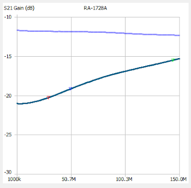
I ran the sweep from 1 to 150 MHz, thinking that surely the 2 meter band would be pushing the limits of the attenuators usefulness.  That was just a guess but I think the measurements confirmed my hunch.  I ran the test with two different attenuations 10dB, and 20dB.  

The upper violet colored trace is with the attenuation set to 10 dB.  The bottom trace (dark green) is with the attenuator set to 20 dB. Notice that while the 10 dB setting slowly increased attenuation with higher frequencies, the 20 dB setting quickly loses more than 5 dB of attenuation as it approaches 150 MHz.

Some people like to think in terms of SWR and this is their plot. Unfortunately, it looks like the SWR is highest right around the 6 meter ham band at 50 MHz.


The NanoVNA Saver program connects your NanoVNA to a computer screen, and is extremely useful unless you have microscopic vision. But the program also does much more than the firmware and 2.8" screen. Below you see 20 dB step reactances for three different frequencies.  Even at 30 MHz there is substantial variance from the desired 50+j0.  


In order to get some idea how accurate the steps are calibrated I measured each at the somewhat arbitrary frequency of 22 MHz.

Step        Measured

0 dB        -0.15

1 dB        -1.16

2 dB        -2.23

3 dB        -3.19

6 dB        -6.07

10 dB        -10.57

20 dB        -19.25

20 dB        -19.35

20 dB        -19.46

Conclusions

The RA-1728A is not a terrible performer but not lab quality either.  I would feel comfortable using it to make rough measurements below 30 MHz.   But keep in mind that the SWR can creep towards 2:1 at some frequencies. The design could be improved in several ways, including shielding between the step switches.  Larry Dodd, K4LED, did a major upgrade to his attenuator with impressive results. Read Larry's article at https://www.101science.com/attenuator.pdf


Monday, February 1, 2021

Rescue that Printer Port ADC

 Probably anyone younger than 30 would be hard pressed to describe a parallel port on a computer.  We used these 25 pin monsters for all sorts of scientific hacking in the days before USB ports.  And so it was 20 years ago when I began promoting and supporting the use of the MAX186 analog to digital (ADC) converter controlled through a parallel port.  The simple circuit is shown below. Given that this IC was an excellent performer and that you could sometimes get the MAX186 as a free sample from Maxim Integrated Circuits for the asking, this was a very attractive option.

MAX186 IC connected to a parallel port.

The MAX186 IC showed up in another printer port connected circuit in KIT118 from kitsrus.com. It appears to still be available from them.  For sometime I have thought about writing a program for the Arduino which would interface with the MAX186 IC pins and allow ADC data to flow through the Arduino USB serial port instead of the printer port.  The issue recently came up again so this time I rummaged around and found a MAX186 IC and an  Arduino Uno.  A few resistors  and 2 capacitors later I had the circuit breadboarded. There is no reason why a Arduino Nano couldn't be used instead of the Uno board. Arduino Nano boards can be purchased for much less than $10.  


If your already-built MAX186 device terminates in a 25 pin connector, you can simply run the 6 jumper wires to the connector from the appropriate pins on the Arduino board.  You can purchase breadboarding jumpers with double male or male/female configurations that will make the job easy. In my test circuit shown above there are only 4 grounded resistors on the 8 channel inputs.  In the real world you will want all of the MAX186 analog pins to have a resistor of 10K or so leading to ground. If left floating, the inputs will produce seemingly random signals and the channels may cross-talk.  

Code

For the latest Arduino code for this project go to https://github.com/radiosky/MAX186_Rescue/tree/main .  

This project is an extension of an earlier effort to make the Arduino act like a User Data Source (UDS) for Radio-SkyPipe described here:

http://cygnusa.blogspot.com/2013/02/arduino-and-radio-skypipe.html

and

http://cygnusa.blogspot.com/2017/06/programming-multiple-channels-in.html

The UDS follows a format outlined here http://radiosky.com/skypipehelp/V2/UDS_model.html .

As written, the code has some limitations.  It always transmits all eight channels of the MAX186 ADC.  All that is needed to change to a different number of channels is to change the code below in the GetD() function so that the '8' in the for statement is the number of channels you want.

void GETD(){

         int u;

         for(u=1 ; u<=8; ++u)

         {

            dat = MaxRead(u-1);

         }

         Serial.print("^^3001"); // This tells RSP to time stamp it

         Serial.write(255); // all commands end with this character.

         return;

  }

To change the sample rate, adjust the delay(100); statement right after the void loop() statement.  Another improvement would be to use an Arduino timer and interrupt to change the sample rate.

The channels selected must begin with channel 1 and be sequential.  You could make any number of modifications and I encourage you to try some.   Let me know what you come up with.

Connecting to Radio-SkyPipe

The point of this is get the data into a strip chart.  Radio-SkyPipe is a strip chart program that can plot a wide number of input sources.  Go to Options and select the Data Source tab.


Set up the number of channels you have indicated in your Arduino code. (Defaults to 8), then press the UDS Set Up button.


To connect to the MAX186 via the Arduino,  we configure a Serial UDS connection. Our Arduino has the ability to follow the UDS commands directly so no UDS exe driver program is necessary.  Thus the EXE File is not used. The Com Port is the com port used by the Arduino. Set it so that the UDS Pushes Data.  This means that Arduino will use it's timing to set the sample spacing. Note the Connection Type is Serial.  


Save your options. That is just about it.  All you need do now is to press the Start button.

Sunday, May 10, 2020

Data Format for ATT-6000 Step Attenuator Module

ATT-6000 electronic rf step attenuator and its serial computer interface.

I am amazed at the useful electronic test equipment the amateur scientist can purchase for so little money these days.  This is just a quick note about the serial command structure used to set attenuation level  on the ATT-6000 step attenuator module.  I purchased my unit new on eBay for less than $30.  This module is probably based on the PE43702 attenuator chip (see below).  The chip has pretty impressive specs, usable up to 6 GHz.  The module I purchased has milled aluminum case and OLED display. It is shown in the above photo hanging in front of its serial port trace.

The program to the left in Fig.1 is the free commercial one that can be downloaded.  I had to ask the vendor to get the download link.  The program does just one thing.  You enter a number and it sends a message to the attenuator that results in the amount of attenuation requested up to the limit of 31.75 dB. Your minimum change can be 0.25 dB.   This program is almost useless as the same thing can be accomplished with a few button presses on the attenuator module itself.

A much more useful feature would be the ability run the attenuator in steps to calibrate a receiver.  The attenuator could be part of a noise figure measurement system,  Programmatic control is desirable. Anyway, I did what any of you might do and ran a serial port monitor to see how the "Digital Attenuator Console" commanded the attenuator to change to X dB attenuation. And it is very simple.

The device operates using 115k baud.  I don't know what microprocessor it uses.  I didn't want to open mine for fear of somehow messing up the connections to the SMA connectors from the board.  If some has pictures or info on the insides please share.  However, there has to be a micro-controller of some sort, even if it is just part of the USB to serial converter.  To set the attenuator to (-) 31.25 dB
you would send it:

Hex  77 76 30 33 31 32 35 0A
 or     
        Ascii  wv03125(Line Feed)

All values are composed of 5 digits preceded by the characters "wv" and followed by a Line Feed character (10d or OAh) Sometimes the device sends back a couple of characters but I don't see any meaning for them.  

If anyone hacks this device and we can reprogram it, I can't wait to change the display.  Currently it shows the attenuation reading in small print on one line and on the next line says "Fre=6,000,000KHz", a useless bit of information, referring to the upper bound of the spec. I would much rather make the top line larger and eliminate the second line.


Friday, September 1, 2017

Radio-Sky Spectrograph works with Radio-Jupiter Pro,

There are a number of ways that Radio-Sky programs can interact with one another.  For example, RTL Bridge can send signal strength from a RTL dongle receiver to Radio-Sky Spectrograph  (RSS) and to the Radio-SkyPipe (RSP) strip chart program.Radio Eyes can start a RSP chart. Radio Jupiter Pro (RJP) can send calculated Jupiter or Solar information to RSS.  Since more people use RSS for Jupiter and solar studies than anything else that I am aware of, it makes sense that RSS can draw this information from RJP when desired.


A new update for RJP facilitates the new Slope Note Pad tool.  With this tool you can easily
run through SPS files and take the slope of a feature (modulation lane, N burst etc.) and
it will grab the corresponding CML IoPhase from RJP and will add it to a list that is exportable
to a spreadsheet.  You just click at the beginning and end of each feature you want the slope
of and your data is compiled for you.

Also be reminded that if you have RJP running along side RSS, and you have the option
set under Options / Network / Radio Jupiter Pro Information Server / Connect to RJP
You can then right click anywhere on your chart and select  Get RJP Charts, which will
produce CMLIo charts, SkyMaps, and AltAz views for that given time. You don't have to
type a time into RJP to do this. Each of these RJP displays has a camera button which
places the image in the clipboard for easy pasting into all of these nice reports you have
been creating. All of these displays popping up in addition to your RSS display takes a lot of screen real estate. Probably would be easiest on a multi-monitor system.

There is a new version of RSS 2.8.45 that you can get to through Help/Check for Updates.

If you have never installed RSS you can get it here:

http://radiosky.com/spec/Spectrograph.exe

For this to work correctly do the following update to RJP:

http://radiosky.com/rjp3/rjp_update_3_8_2.exe

In RJP you want to make sure the Information Server (JIS) is running on start up.
This is found under Tools / Jupiter Information Server.


Finally, you could use the JIS feature to grab the info for any program by making a TCP connection to the IP and Port shown.  In the Jupiter Info Server Options you can push out the selected info (in string format)  by using the Push option or by Sending a "J" to the server from your client you can get the JIS to send you the string.  Try it using a terminal program.

Added September 2. 2017
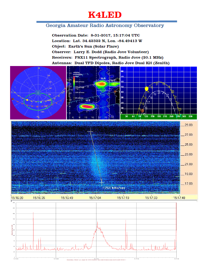
Larry Dodd, K4LED, used the features described above to make the nice solar observation report below;


Have Fun.

Jim

RF Noise Source NF-1000 SZ evaluation

  I have been working on an automated step calibrator project in recent months, so I was excited when I saw the device shown above on eBay. ...