Some time ago I developed a connection to Radio-SkyPipe to an Arduino controller via a serial connection. By placing enough "intelligence" in the Arduino to communicate directly with RSP using the UDS protocol, we eliminate the complexity of having a specially written UDS "driver" program that sits between RSP and the data collection device (the analog to digital converter on the Arduino). If you haven't read that post please do. It will make this post seem much more intelligible. Of course, the range of the serial connection is limited unless we use a modem (remember those?) Fortunately, Arduino Unos support an Ethernet shield which can then be connected to a LAN or WAN.
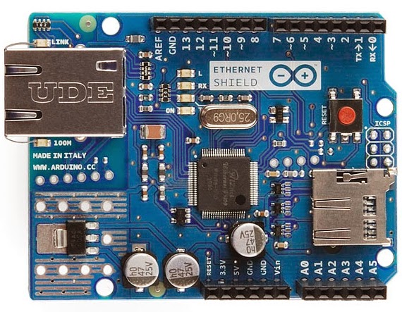 |
| Image of the official Ethernet shield taken from the arduino.cc website. |
The official Arduino Ethernet shield costs about $38. I advise that you buy an official board as I have heard stories of incompatibilities with some of the cheaper knock-offs. There is also a WiFi shield that can be purchased for Arduino but I do not have one to test. I assume operation would be similar to the Ethernet shield. For my purpose, I have a router at the remote location and can just plug into that directly. A SD card slot is available on the Ethernet shield and it could be very handy for storing data locally in case there is a network failure. A 4 Gig SD card could handle more than 10 years worth of data from one channel at 10 samples/second. The code I am passing on to you right now doesn't store the data locally, but perhaps I can add that feature in a future post.
You must include the Libraries needed by the Ethernet shield; SPI and Ethernet.
You must apply the right settings to your Ethernet shield. There should be a sticker on the board that holds the MAC number for the chip. You will need that. You will also need the IP address that you want the board to use. The gateway and subnet mask can be retrieved from your router. The docs say they are optional but I included them.
byte mac[] = {
0x90, 0xA2, 0xDA, 0x0D, 0xFB, 0x03 };
IPAddress ip(192,168,1,60);
IPAddress gateway(192,168,1,1);
IPAddress subnet(255, 255, 255, 0);
// the default UDS port = 1377
EthernetServer server(1377);
Initialize the Ethernet device in your setup { } routine
Ethernet.begin(mac, ip, gateway, subnet);
// start listening for clients
It was a simple matter to change the original serial code to the Ethernet version by replacing Serial.print() and similar statements with client.print().
I did have to move the workings of the old data fetch and send routine GETD() to within the main loop so the client object would be in scope to send the data back to RSP. So when you see two identical blocks of code it is because I could not keep them as a separate subroutine, probably because I am new to this. It makes me feel like a baaaad programmer.
At first I had a problem getting RSP to re-connect to the Arduino after I had canceled a connection. It was necessary to add the following lines to break the connection from the Ethernet boards perspective.
if (!client.connected()) {
//Serial.println();
//Serial.println("disconnecting.");
client.stop();
}
Note there are //Serial.print() statements peppered through the code. These can be uncommented if you want to use them for debugging. Just uncomment the appropriate lines, and use the Arduino IDE Serial Monitor to get feedback as you work on your program.
Of course, you will change the analog data read to whatever you want to record. This is just a bare bones program. You could add DHCP, additional channels, a local clock for timestamping data saved to SD card. A Telnet or Web Server interface could allow you log in and turn things off and on at the remote site. There are already libraries and example code out there to piece together a lot of functionality using not too much electrical power. Let me know what you come up with.
Get the sketch here.
 |
| Obligatory 2D etch-a-sketch using a pot. |


