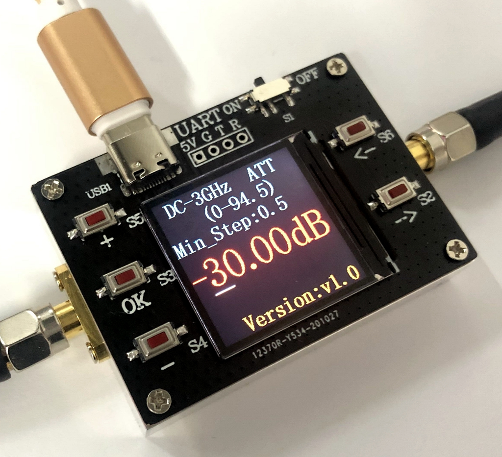
I've been working on a simple step calibrator design for the Radio JOVE 2 project. The attenuator will be controlled via the Radio-Sky Spectrograph program. Our primary interests lie in the frequency range from about 15 to 30 MHz. The current design incorporates multiple 32 dB attenuator modules. Recently, I found the DC-3G-90DB-V2 attenuator module on eBay and quickly ordered one in hopes that it could simplify our design. The module sold with the following specs:
- DC to 3 GHz frequency range
- 94.5 dB maximum attenuation
- Power supply voltage: +5V (TYPE-C power supply)
- Input and output impedance: 50 ohms
- Minimum attenuation step: 0.5DB
- Size: Length*Width=5.6*4CM (excluding SMA size); Height: 1.5CM
- Supports both USB and TTL serial communication
- RF input & output ports: SMA female connector
The DC-3G-90DB-V2 has its own OLED color display, as shown above, and can be controlled by 5 push buttons. The USB-C connection powers the unit and if connected via computer you can set the attenuation via the 115kB USB-serial connection. In order to get my Win 10 computer to see the USB com port, I had to install the STM virtual com port driver at:
I used the simple serial port monitor in the Arduino IDE, but you can use any serial terminal program to access the com port. Make sure you have the terminal program set up to send a carriage return and line feed (CRLF) with each command. The advertised format is ATT-xx.xx plus Enter. The device will return with ATT-OK for a successful command. Even though the attenuator only produces attenuation in half dB steps, it is possible to set the fractional portion of the attenuation to values other than 0 or 5. I see no reason for having to display the attenuation to the hundredths place other than it looks impressive to the buyer. I spent quite a bit of time trying to get the serial control to work, but it looks as if my seller has now added information to the listing that would have saved me some experimentation.
An odd thing about the format is how it interprets the command if you don't use the entire four digits and decimal.
ATT-34.50 + CRLF produces -34.50
ATT-34.5 + CRLF produces -34.50
so the last digit is totally unnecessary.
Assume the current attenuation is displayed as "-34.50"
ATT-4 + CRLF produces -44.50 !
So sending only one digit will only affect the tens of decibels. In order to change the units column, you must specify two digits, the tens and the units.
Assume the current attenuation is displayed as "-34.50", then
ATT+47 + CRLF produces -47.50
In order to toggle the half of a decibel digit you must specify either xx.0 or xx.5. You can specify any two digits in the fractional part and the module will obediently display it, however, the attenuator chips will not be able to comply with anything other than zero or 0.5 decibels. If you always specify xx.x you will be fine but be careful using shortcuts from your terminal program or code.
I have not tried communicating with the DC-3G-90DB-V2 via the TTL connection. This will require soldering a header to access the TTL serial pins. When I (or you) do, lets not forget that the TTL serial connection will run at 9600 baud, something that just appeared on the vendor's listing.
There is a Problem!
The Radio JOVE calibrator will be composed of a broad banded radio frequency noise source fed through the computer controlled step attenuator. One of the things we want see with our calibrator is how sensitive the receiver is to weak signals from Jupiter. It is necessary that we can control the signal level from the calibrator to a very low level. There is a broad assumption that the noise spectrum generated is as flat as possible. I was thus very disappointed to see that the DC-3G-90DB-V2 produces noise of its own.

 |
| Noise generated by the microprocessor circuitry in the DC-3G-90DB-V2 attenuator module. |
Screwdriver time
The DC-3G-90DB-V2 is built upon a very nice milled case. Four tiny screws and standoffs support the Lucite cover that protects the screen.
 |
| Inside the DC-3G-90DB-V2 step attenuator. The milled box on the left contains three attenuator chips with their identifying marks scratched out. Likewise, the microprocessor (MPU), a STM32 variety, has its model obscured. The ribbon cable takes power and control lines from the micro board to the attenuator board. |
This is the layout I was hoping to find. Had the attenuator chips resided on the same board as the MPU, there would be no way to isolate the attenuator rf signal path from the noisy microprocessor. I thought it might be possible to shield the attenuator board with thin sheet of brass. The signal levels on the ribbon cable change only when the attenuators are set to a new value and thus should not be conductors of the rfi ,(radio frequency interference)
 |
| A thin sheet of hobby brass is cut with scissors to act as a rf shield between the MPU and attenuator boards. The corners are removed to allow screws to pass and a section is removed to accommodate the ribbon cable. The side facing the MPU board has a layer of electrical tape to prevent any shorting. |
 |
| Shield in place and ready to be screwed down. |
Before closing things up I tried to improve the brass edge with a bit of DeoxIT 5.
I am happy to say that this inexpensive fix totally eliminated the problem in 15 to 30 MHz band. I cannot detect the numerous interference spikes using our software. Below 5 MHz things look better but not perfect. I did not run tests above 30 MHz and so cannot vouch for the usefulness of this hack at VHF and above. I suspect the self induced - rfi problem fades in significance at higher frequencies/harmonics and also when the attenuator is being used for tasks other than with a weak signal calibration. I hope the manufacturer will see this as a way they can improve future versions of their product.
 |
| View showing the complete absence of the 21.27 MHz spur after applying the brass shield. |


No comments:
Post a Comment