 |
| The eBay purchased step attenuator being probed by the mighty NanoVNA. |
You may have noticed the sudden bounty of 50 ohm step attenuators on eBay for about $30. I am not sure they are all branded the same way but the one I purchased had the brand name "Tronson" and the model number RA-1728A. This device seems outwardly to be based on the common Kay brand attenuators that have been around for many decades.
The heavy metal case is easily taken apart with 6 screws, and that is of course the first thing I did. Inside, there were no real surprises, except I was thinking there might be a circuit board. The attenuator is hand wired using an extremely thin gauge wire that appears to be tinned. The attenuators are pi configured resistors constructed right on the toggle switch body. Many commercial and homebrew rf step attenuators are constructed this way. The unit uses 1% 1/4 watt resistors, except on the 20 dB steps where the top of the pi is a 5% 100K resistor. Not sure why they cut that corner..
 |
| Inside the step attenuator. A bit disappointing. |
The workmanship isn't the best, but it is hard to say how much that affects the unit's operation below 30 MHz. I made a few measurements using my $50 NanoVNA. The NanoVNA appears to be fairly accurate below 150 MHz, despite the low cost. There are plenty of blogs and videos out there discussing these amazing little tools. I had to use two adapters on each end of the attenuator to match the SO-239 sockets to the tiny SMA connectors on the NanoVNA. The adapter reactances couldn't be included in the calibration so may have some affect on the measurements especially at higher frequencies.
I ran the sweep from 1 to 150 MHz, thinking that surely the 2 meter band would be pushing the limits of the attenuators usefulness. That was just a guess but I think the measurements confirmed my hunch. I ran the test with two different attenuations 10dB, and 20dB.
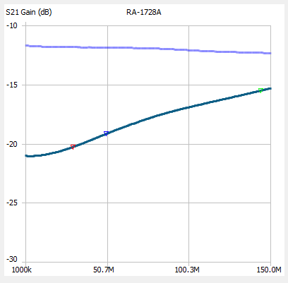 |
| The upper violet colored trace is with the attenuation set to 10 dB. The bottom trace (dark green) is with the attenuator set to 20 dB. Notice that while the 10 dB setting slowly increased attenuation with higher frequencies, the 20 dB setting quickly loses more than 5 dB of attenuation as it approaches 150 MHz. |
 |
| Some people like to think in terms of SWR and this is their plot. Unfortunately, it looks like the SWR is highest right around the 6 meter ham band at 50 MHz. |
The NanoVNA Saver program connects your NanoVNA to a computer screen, and is extremely useful unless you have microscopic vision. But the program also does much more than the firmware and 2.8" screen. Below you see 20 dB step reactances for three different frequencies. Even at 30 MHz there is substantial variance from the desired 50+j0.

In order to get some idea how accurate the steps are calibrated I measured each at the somewhat arbitrary frequency of 22 MHz.
Step Measured
0 dB -0.15
1 dB -1.16
2 dB -2.23
3 dB -3.19
6 dB -6.07
10 dB -10.57
20 dB -19.25
20 dB -19.35
20 dB -19.46
Conclusions
The RA-1728A is not a terrible performer but not lab quality either. I would feel comfortable using it to make rough measurements below 30 MHz. But keep in mind that the SWR can creep towards 2:1 at some frequencies. The design could be improved in several ways, including shielding between the step switches. Larry Dodd, K4LED, did a major upgrade to his attenuator with impressive results. Read Larry's article at https://www.101science.com/attenuator.pdf


No comments:
Post a Comment