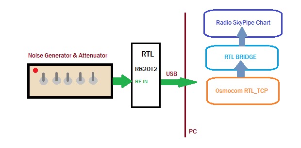
Its been a while now since I wrote RTL Bridge and made it possible to pipe the total power from the receiver bandpass to Radio-SkyPipe (RSP) for display in a strip chart. It occurred to me that I had never tested this in any more than a very superficial way. If it works in some predictable way, then the dongle-RSP combo might be useful for making power measurements. I even had a use for it, to measure the insertion loss of an inexpensive FM band trap at HF. I bought ten of the traps shown below for $0.67 each from MCM Electronics. The front ends of RTL based receivers are wide open (no rf filters) and thus with their limited dynamic range, are susceptible to overload from nearby commercial radio stations. An effective trap can help this problem.
For this and most things, I use the RTL dongles with a 2 MSPS sample rate. This translates to a 2 MHz wide bandwidth. For this test I have the gain set at maximum for the R820T2 tuner. The center frequency is 20 MHz which means I am using the low frequency enabled version of the rtlsdr.dll. I use 20 MHz because I have a noise source calibrated at that frequency (RF2080 C). I also have a RF2010 noise generator with a built in binary step attenuator capable of 31dB total attenuation. The noise temperature ranges from about 3000 Kelvin to 3200000 K.
 |
| Basic test setup for determining how well RTL + Radio-SkyPipe can measure rf power. |
"Its not linear", I thought. It looks like it has a sinusoidal shape. If tried to find a function that makes the data conform with reality. I would then apply the function to the incoming data using the RSP Equation feature so that the data would scale to something meaningful like noise temperature or dBm. Even without calibration, RSP should be able to tell me how much loss incurs from inserting the FM Trap in line to the antenna (or noise source ).
I tried a couple of curve fitting calculators on the web to see if I could get a regression fit of some kind, Unfortunately none of the "curve fitters" made any improvement over a straight line fit. Divergence from my hoped for straight line may on the low end just be due to approaching the HF noise figure limitation of the RTL. On the high end we may be reaching compression. There is no filter in line with the 25000K noise source so the input of the dongle is exposed to a very wide band noise signal.
Good Enough
Along the middle 60% there is very good linearity which indicates that Dongle->RTL Bridge->Radio-SkyPipe combo performs well as a power detector at 20 MHz. Below about -93 dBm or 18000K and above -77 dBm or 772000K linearity suffers some.So back to the FM Trap insertion loss problem. The question again is "Will the trap degrade my use of the RTL Dongle at 20 MHz?". So I measured using a noise source with a temperature that laid along the straight part of the line. No need for calibration because we are just interested in a relative measurement. I found the loss of the trap is below the threshold of what I can measure which is about a half dB. That is a totally acceptable loss, provided that the trap is doing what it should do, reduce the signal across FM band 88 - 108 MHz. I haven't measured the bandpass above and below the FM band but I intend to try. For kicks I want to use the dongle and a broadband noise source to measure the filter.


No comments:
Post a Comment